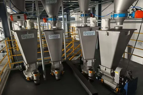
In continuous manufacturing, a feeder does far more than move material from a hopper into a process. It determines whether the formulation entering an extruder, mixer, reactor, granulator, or packaging line remains consistent from one minute to the next. A small feeding error can alter color, mechanical strength, conductivity, flavor, active-ingredient concentration, moisture control, or final product yield. These effects become especially costly when the material being dosed is expensive, the allowable tolerance is narrow, or the line operates for thousands of hours per year.
A single screw loss-in-weight feeder addresses this challenge by combining a mechanically simple screw metering device with continuous weight measurement and closed-loop control. The screw provides controlled material movement, while load cells and a controller measure the actual reduction in hopper weight over time. When the measured mass flow differs from the target, the controller changes screw speed to correct the deviation. The result is a feeding system that responds to real material behavior rather than assuming that every screw revolution always carries the same mass.
This guide explains how the technology works, where it creates the most value, which materials are suitable, how it compares with alternative feeders, and what production teams should verify before purchasing. It also shows how Transcell applies weighing, control, mechanical design, and application testing to develop practical feeding solutions for demanding industries.
What Is a Single Screw Loss-In-Weight Feeder?
A single screw loss-in-weight feeder is a gravimetric metering system that continuously weighs a hopper and adjusts one rotating screw to maintain a target mass flow rate.
The phrase “single screw” describes the material discharge mechanism. One screw rotates beneath the hopper and transports material toward the outlet. The phrase “loss-in-weight” describes the measurement method. The feeder frame, hopper, material, drive, and metering section are supported by a weighing system. As material leaves the hopper, the system measures the rate at which total weight decreases.
This distinction is important. A screw by itself is a volumetric device because each revolution displaces a certain volume. When the same screw is installed on a weighing platform and controlled according to actual weight loss, it becomes part of a gravimetric system. The feeder can therefore compensate for reasonable changes in bulk density, particle packing, moisture, headload, and screw fill. Instead of relying only on motor speed, it closes the loop around the quantity that usually matters to the formulation: mass per unit time.
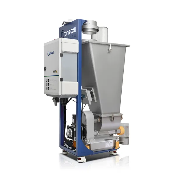
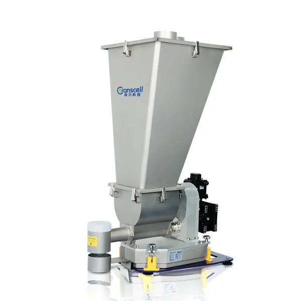
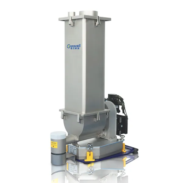
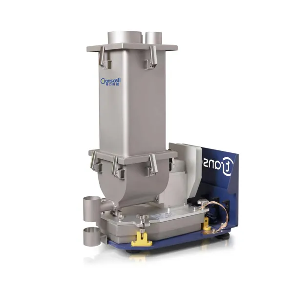
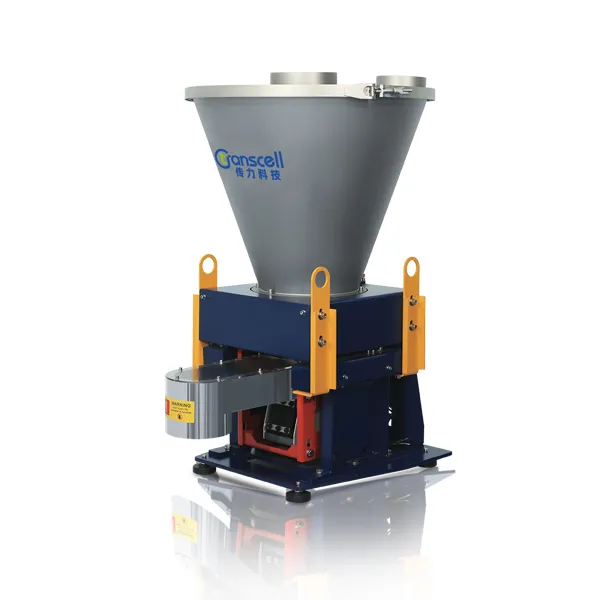
For production teams evaluating equipment, Transcell’s single screw feeder is designed for precision metering and continuous conveying of granular materials and mixtures of granules and powders. The standard product listing includes 60 L or 120 L metering-bin options, a 15 L U-shaped hopper, SS304 material-contact construction, a 1 kW 380 V servo motor, an ambient operating range of 0–40°C, and a material-temperature range of 0–50°C. These are standard parameters rather than universal limits, so the final configuration should be confirmed against the material, required rate, cleaning procedure, plant environment, and control architecture.
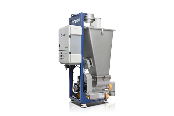
How Does a Single Screw Loss-In-Weight Feeder Work?
A single screw loss-in-weight feeder works by calculating weight loss per unit time, comparing the measured value with a feed-rate setpoint, and changing screw speed to reduce the error.
The operating cycle can be understood in six stages.
Setpoint entry: The operator or production control system enters the desired feed rate, such as kilograms per hour.
Continuous weighing: Load cells measure the combined weight of the feeder assembly and the material inside the hopper.
Mass-flow calculation: The controller calculates how quickly the measured weight is decreasing. In simplified form, mass flow equals the change in weight divided by the change in time.
Closed-loop correction: If actual weight loss is below the target, the controller increases screw speed. If actual weight loss is above the target, it reduces screw speed.
Refill control: When hopper weight reaches a lower threshold, a refill device adds material. Because weight rises during refill, the controller temporarily relies on a controlled volumetric mode or historical operating data.
Return to gravimetric operation: After refill stabilizes, the controller resumes normal loss-in-weight measurement and correction.
The quality of this cycle depends on more than the nominal resolution of a load cell. The weighing signal must be stable, the feeder must be isolated from external forces, the screw must fill consistently, the refill must be fast and repeatable, and the control algorithm must distinguish real mass-flow changes from vibration or disturbance. This is why a loss in weight feeder should be evaluated as a complete mechanical, weighing, and control system rather than as a screw mounted on a scale.
Which Components Determine Feeding Performance?
The performance of a single screw loss-in-weight feeder is determined by the interaction of the hopper, flow aid, screw, drive, weighing system, controller, refill device, and mechanical connections.
Hopper and Transition Geometry
The hopper must deliver material to the metering zone without bridging, rat-holing, segregation, or uncontrolled flooding. Steep walls and a properly shaped transition can help maintain movement, but geometry should be selected around actual flow properties. A design that works for free-flowing pellets may fail with cohesive powder, low-density flakes, or material that becomes sticky as temperature rises.
Agitation or Flow Assistance
An agitator can prevent stable arches from forming above the screw. However, aggressive agitation can compact certain powders, break fragile particles, generate heat, or transmit force into the weighing system. The objective is not maximum agitation; it is the minimum controlled action required to produce repeatable screw filling.
Screw Geometry
Screw diameter, pitch, flight form, clearance, surface finish, and length influence capacity, pulsation, shear, residual material, and turndown. A large screw operated too slowly may produce pronounced discharge pulses. A small screw operated near maximum speed may not fill completely and may create unstable output. The best operating point is normally inside the practical speed range, with enough reserve for automatic correction.
Drive and Speed Control
A stable variable-speed drive allows the controller to make fine corrections. Servo control can be valuable where rapid response and repeatable low-speed operation are required. The motor and gearbox must also provide enough torque for startup, changes in headload, and occasional material compaction without being oversized to the point that low-speed control becomes poor.
Load Cells and Mechanical Support
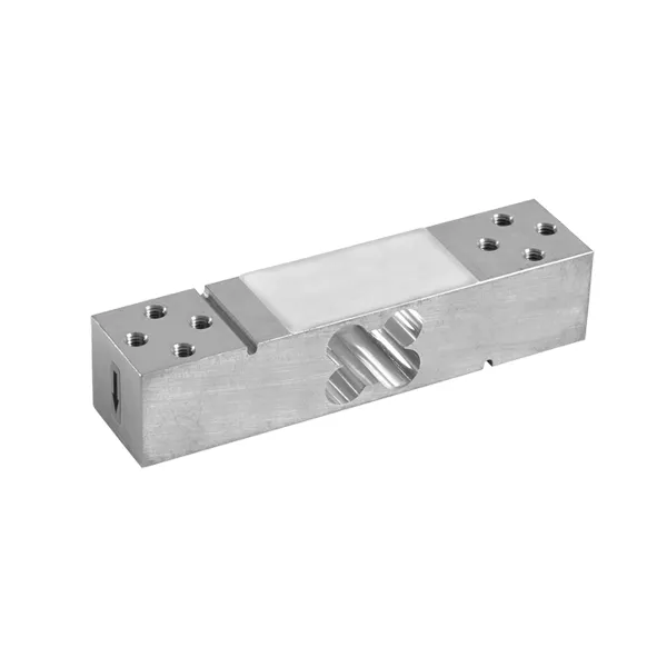
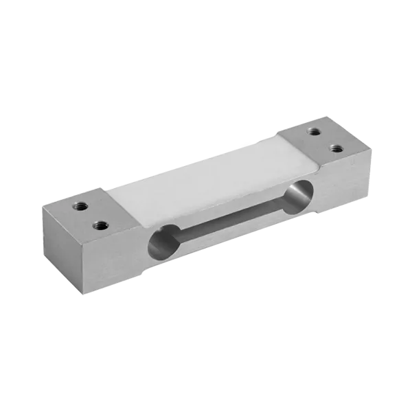
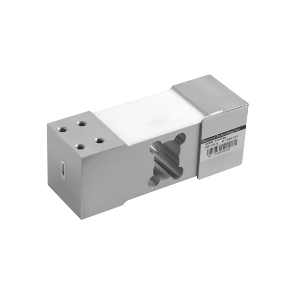
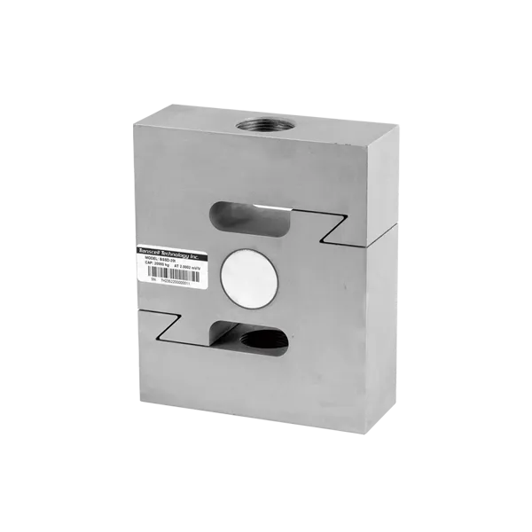
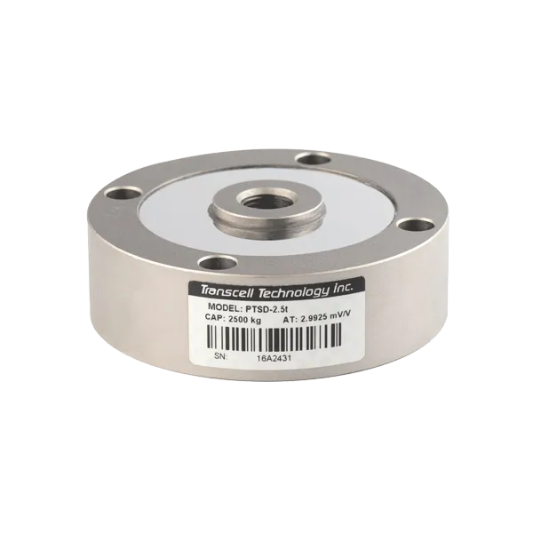
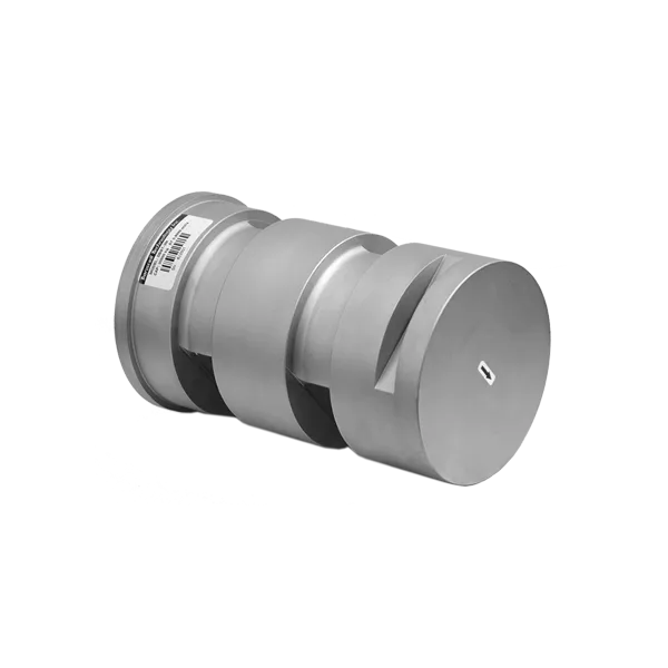
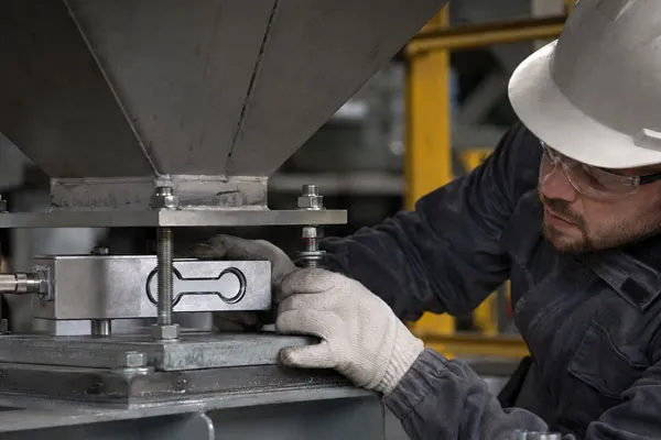
The weighing system must resolve small changes in material weight while supporting the feeder’s dead load. Flexible inlet and outlet connections are essential because rigid ducts, cables, hoses, or dust sleeves can bypass the load cells and introduce measurement error. Nearby machinery, airflow, floor vibration, and poorly supported refill equipment can also influence the signal.
Controller and Algorithm
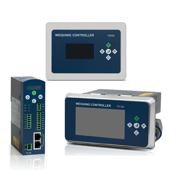
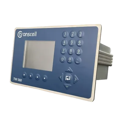
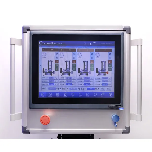
The weighing controller calculates mass flow, filters disturbances, manages refill, tracks screw speed, records alarms, and communicates with the wider line. It should offer enough response to correct real changes without chasing noise. Useful functions may include recipe storage, automatic tuning, trend data, deviation alarms, material-total accumulation, remote setpoint control, and integration with PLC or supervisory systems.
Why Choose a Single Screw Instead of a Twin Screw?
A single screw is often the preferred metering device when the material is granular or reasonably free-flowing and the process benefits from simpler cleaning, lower wear, lower spare-part cost, and gentle handling.
Twin screws are valuable for cohesive, sticky, floodable, or difficult powders because intermeshing or self-wiping profiles can promote positive movement. However, twin screws are not automatically more accurate. Accuracy is produced by the complete feeding system, including repeatable screw filling, correct sizing, stable weighing, fast control, and suitable refill behavior.
For pellets, granules, crystalline materials, and many granule-powder blends, a well-selected single screw can provide stable output with fewer parts. It is easier to disassemble, easier to inspect, and generally less expensive to replace than a matched twin-screw set. The reduced mechanical contact may also be favorable for particles that should not be crushed or heated unnecessarily.
The choice should be based on a material trial rather than a general rule. A powder described as “free-flowing” in a datasheet may behave differently after storage, pneumatic conveying, temperature change, or moisture exposure. Likewise, a granular material may contain enough fines to bridge or compact. Testing should reproduce actual feed rate, refill method, hopper level, material condition, run duration, and downstream backpressure.
What Materials Are Best Suited to Single Screw Gravimetric Feeding?
Single screw gravimetric feeding is best suited to materials that can fill the screw consistently without severe bridging, smearing, packing, or uncontrolled flooding.
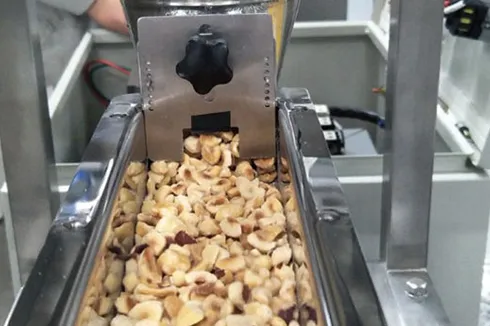
Typical candidates include plastic pellets, masterbatch granules, additives blended with granules, crystalline chemicals, salt-like materials, detergent granules, food particulates, fertilizer granules, mineral granules, and selected powders with adequate flowability. Some mixtures of pellets and powder can also perform well when the hopper prevents segregation and the screw geometry maintains a representative composition.
Material suitability should be assessed using several properties:
Bulk-density range: Gravimetric control compensates for density change, but very large or abrupt changes can still affect screw fill and controller response.
Particle-size distribution: Wide distributions may segregate during conveying or refill, changing the composition delivered by the screw.
Flowability: Cohesive materials may bridge, while highly aerated powders may flood.
Compressibility: Some powders compact under hopper pressure or agitation, causing a changing mass-per-revolution relationship.
Moisture sensitivity: Hygroscopic materials may become sticky or form lumps during a long run.
Abrasiveness: Mineral fillers can wear flights, tubes, seals, and surface finishes.
Fragility: Fibers, flakes, and brittle particles may be damaged by a screw and may be better served by a vibratory feeder.
Temperature: Heat may change viscosity, stickiness, or bulk density and may require insulation or special seals.
Sanitation requirement: Food and pharmaceutical applications may require hygienic construction, validated cleaning, polished surfaces, special elastomers, and documented material traceability.
Where Is the Technology Used?
Single screw loss-in-weight feeders are used wherever continuous production requires controlled addition of a granular or moderately flowing ingredient by mass.
Modified Plastics and Compounding
In plastics compounding, feeders meter resin pellets, color masterbatch, stabilizers, flame retardants, impact modifiers, processing aids, and mineral-filled blends into an extruder. The economic value is highest when an additive is expensive or when variation affects color, mechanical properties, surface finish, flame performance, or certification.
Cable Compounds
Cable formulations may contain polymers, fillers, stabilizers, flame-retardant systems, pigments, and process aids. Accurate continuous ratios help maintain electrical, thermal, smoke, and mechanical performance while reducing the need to overfeed costly components.
Chemical Production
Chemical lines use gravimetric feeders for catalysts, salts, additives, granular intermediates, and blending ingredients. Closed-loop mass control supports recipe consistency and provides material-total data for traceability and reconciliation.
Food and Pet Food
Food processes may require controlled addition of salt, sugar, grains, premixes, vitamins, flavors, or functional ingredients. Equipment design must account for sanitation, allergen changeover, dust, ingredient fragility, and the required cleaning method. A single screw can be appropriate when it moves the product gently and can be disassembled efficiently.
New Energy Materials
Battery and other new-energy processes often use high-value powders and additives. Although difficult cohesive powders may require twin screws or specialized flow aids, single screws can handle suitable granules, carriers, and free-flowing components. The weighing and control architecture should be selected for the plant’s vibration, dust, containment, and automation requirements.
Pharmaceutical and Nutraceutical Production
Continuous pharmaceutical manufacturing requires stringent control, documented material handling, and validated cleaning. A single screw may be selected for free-flowing excipients or granules, but the design must be evaluated for containment, contact materials, disassembly, surface finish, calibration, and data integrity. Equipment suitability is determined by the complete process and regulatory strategy, not by feeder type alone.
How Should Feeder Accuracy Be Defined?
Feeder accuracy should be defined through repeatability, linearity, stability, sampling time, setpoint range, and material conditions rather than through one isolated percentage.
A statement such as “±0.5% accuracy” is incomplete unless the test method is specified. The result can change depending on whether samples are collected over one second, thirty seconds, or ten minutes. Long samples can hide short-term pulsation, while very short samples may exaggerate normal measurement noise. Production teams should therefore request test data that matches the time scale at which downstream quality is affected.
Four measures are especially useful:
Repeatability: How consistently the feeder delivers the same rate under unchanged conditions.
Linearity: How closely average delivery follows the requested setpoint across the operating range.
Stability: Whether performance drifts over hours because of temperature, material buildup, mechanical change, or sensor effects.
Refill performance: Whether the feeder maintains acceptable delivery while the hopper is being replenished.
A feeder should also be evaluated at minimum, normal, and maximum rates. At low rates, individual screw flights may create visible pulsation. At high rates, incomplete filling, motor load, or outlet restriction may limit performance. The usable turndown is therefore the range over which the feeder meets the process requirement with the actual material, not simply the ratio between published maximum and minimum motor speeds.
Single Screw, Twin Screw, Vibratory, and Volumetric Feeder Comparison
The best feeder is the design that produces repeatable material movement and measurable process value under the actual material and operating conditions.
| Feeder Type | Measurement Principle | Best-Suited Materials | Main Strengths | Main Limitations | Typical Selection Trigger |
|---|
| Single screw loss-in-weight | Continuous mass measurement with one screw | Pellets, granules, crystals, selected powders and blends | Simple, cleanable, economical, gentle, closed-loop mass control | May pulse at very low speed; not ideal for highly cohesive or sticky powders | Accurate continuous dosing of reasonably flowing solids |
| Twin screw loss-in-weight | Continuous mass measurement with two screws | Cohesive, floodable, sticky, or difficult powders | Positive movement, improved screw filling, reduced low-rate pulsation | More parts, higher cleaning effort, higher screw replacement cost | Difficult powder flow or low-rate powder dosing |
| Vibratory loss-in-weight | Continuous mass measurement with a vibrating tray | Fibers, fragile particles, abrasive or easily damaged materials | Gentle handling, no rotating screw in the product stream | Performance depends strongly on material response to vibration | Product damage or screw wear must be minimized |
| Volumetric single screw | Screw speed calibrated to volume per revolution | Uniform-density, free-flowing materials | Lower initial cost and simpler control | Cannot directly detect density-related mass-flow drift | Accuracy is secondary and material remains consistent |
How Do You Specify the Right Single Screw Feeder?
Correct specification begins with the material and process requirement, then converts those requirements into mechanical, weighing, control, cleaning, and integration criteria.
A useful request for quotation should include more than a material name and maximum kilograms per hour. Suppliers need enough information to reproduce the application and select a screw that operates in a stable range.
Material identity and composition: Include trade name, ingredients, particle size, bulk density, moisture, and safety data.
Required feed-rate range: State minimum, normal, and maximum rates, plus the unit of mass per time.
Accuracy objective: Define the sampling interval, setpoints, and acceptable deviation.
Operating mode: Continuous, batch, recipe change, master-slave ratio, startup, shutdown, and purge requirements.
Refill method: Manual bags, vacuum conveying, pneumatic conveying, gravity refill, or upstream hopper.
Available headroom: Include floor elevation, extruder inlet height, maintenance clearance, and surrounding equipment.
Plant environment: Temperature, humidity, washdown, dust classification, corrosive atmosphere, and vibration sources.
Product-contact requirements: Stainless-steel grade, elastomers, surface finish, food-contact documentation, or contamination control.
Cleaning procedure: Dry clean, vacuum, wipe-down, wet clean, clean-in-place, or full disassembly.
Controls: PLC brand, communication protocol, remote setpoint, data logging, alarms, interlocks, and cybersecurity expectations.
Material testing should be included when the powder is unusual, the rate is low, the acceptable deviation is narrow, or product quality is expensive to verify. A strong test protocol records actual delivered weight, screw speed, hopper level, refill events, motor load, environmental disturbance, and any change in material condition during the run.
What Installation Details Protect Gravimetric Accuracy?
Installation protects gravimetric accuracy by ensuring that the load cells measure only the feeder and material rather than forces from ducts, cables, vibration, airflow, or surrounding equipment.
The feeder should be mounted on a stable structure with enough stiffness to prevent deflection. Flexible connections at the inlet and outlet must remain genuinely flexible throughout movement, temperature change, and maintenance. A fabric sleeve that becomes tight after reassembly can create a force path that bypasses the scale. Electrical cables and air lines should have service loops and should not pull on the weighing frame.
External vibration should be assessed during real plant operation. Nearby extruders, granulators, blowers, vacuum receivers, and material-handling equipment may introduce periodic forces. Isolation and signal filtering can help, but software cannot fully correct a weak mechanical installation. Strong airflow around an open or lightly covered hopper can also disturb small weight measurements.
The refill device should not rest on or mechanically bind the weighed feeder unless it is included intentionally in the weighing design. Refill should be fast enough to limit the period of non-gravimetric control, but not so aggressive that material impact overloads the hopper, fluidizes powder, or produces long stabilization times.
How Do Refill Strategy and Hopper Size Affect Performance?
Refill strategy affects performance because every refill temporarily changes hopper weight, material headload, packing condition, and the controller’s measurement mode.
A large hopper reduces refill frequency but increases dead load, equipment size, material residence time, and the weighing range required. A small hopper improves weight resolution relative to the live material but requires more frequent refill. The correct size balances these effects against consumption rate and refill capability.
For example, a line consuming 300 kg/h uses 5 kg per minute. A 60 L hopper holding a material with an apparent bulk density of 0.6 kg/L contains roughly 36 kg when full, before accounting for practical fill level and hopper geometry. That represents about 7.2 minutes of material at 300 kg/h. This simple calculation helps estimate refill frequency, but the actual usable inventory is lower because the feeder needs upper and lower control limits and must avoid running the screw empty.
The refill valve or conveying system should deliver material consistently and stop cleanly. Excessive dribble extends the disturbance period. A refill that aerates powder may temporarily reduce bulk density and alter screw fill after the gravimetric cycle resumes. Good control logic can reduce the effect, but mechanical refill behavior remains important.
What Maintenance Practices Preserve Accuracy?
Preventive maintenance preserves feeder accuracy by keeping material flow, screw geometry, weighing mechanics, and control feedback within the conditions established during commissioning.
Routine inspection should cover screw wear, buildup, bearings, seals, gearbox condition, agitator clearance, flexible connections, load-cell mounts, cables, grounding, and refill components. Abrasive material can enlarge screw clearance or change flight shape gradually, which changes capacity per revolution and forces the controller to operate at higher speed. The gravimetric loop may compensate for some wear, but reduced speed reserve and increasing variability are warning signs.
Operators should monitor trends rather than waiting for a final-product failure. Useful indicators include rising average screw speed at the same setpoint, more frequent high-speed alarms, longer refill stabilization, increased deviation, repeated low-weight alarms, or changes in motor load. Comparing these values against a known-good baseline can identify buildup or material-flow deterioration before the line stops.
Calibration and verification schedules should reflect production risk. A high-value pharmaceutical ingredient may require a different control plan from a low-cost mineral filler. Verification should use traceable test weights and a documented procedure, but feeder performance should also be confirmed by collecting and weighing actual material over a defined interval.
How Can You Calculate the Business Value?
The business value of a single screw loss-in-weight feeder is the combined financial effect of reduced overfeeding, fewer off-spec products, lower rework, faster changeovers, improved traceability, and higher line availability.
Consider an illustrative compounding line that produces 10,000 metric tons per year and uses an additive at 5% of final output. The target additive consumption is 500 tons per year. At an additive cost of USD 3,000 per ton, annual target spend is USD 1.5 million.
If a process intentionally overfeeds by 2% to protect against volumetric uncertainty, it uses an extra 10 tons of additive, costing USD 30,000 per year. At 3.5% overfeed, the extra quantity becomes 17.5 tons and USD 52,500. At 5%, it becomes 25 tons and USD 75,000. If a gravimetric system allows the plant to operate with a 0.5% margin, the extra use is 2.5 tons, or USD 7,500. The annual material difference versus a 3.5% case is USD 45,000.
This model is not a universal promise. It is a transparent calculation that must be replaced with the plant’s actual output, recipe ratio, ingredient price, historical deviation, scrap rate, and operating hours. It also excludes potential benefits from improved product consistency, reduced laboratory testing, fewer customer claims, and more stable downstream operation.
A practical ROI calculation can use the following structure:
Annual material saving = annual target ingredient mass × reduction in overfeed percentage × ingredient cost per unit mass.
Simple payback period = installed project cost ÷ annual net saving.
Installed project cost should include the feeder, support frame, refill equipment, controls, wiring, commissioning, validation, operator training, spare screws, and planned downtime. Annual net saving should subtract maintenance, calibration, and any additional energy or service cost.
Why Work with Transcell on a Single Screw Feeding Project?
Transcell approaches precision feeding as an integrated weighing and control application that must be configured around material behavior, process targets, installation conditions, and long-term service requirements.
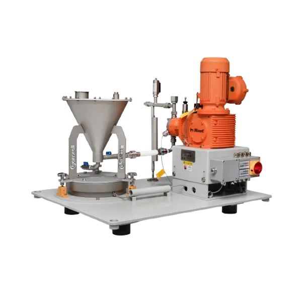
Transcell’s loss-in-weight product range includes single screw, double screw, micro, vibrating, and liquid configurations, allowing the feeding mechanism to be selected around the material rather than forcing every application into one platform. The company also provides load cells, weighing instruments, controllers, and industrial intelligent control systems, which supports coordination between mechanical metering, signal measurement, automation, and plant data.
For a useful consultation, provide representative material, feed-rate range, expected accuracy, refill arrangement, process height, cleaning method, electrical standard, and communication protocol. A material trial is especially valuable when the ingredient is cohesive, abrasive, fragile, aerated, variable in density, or used at a low rate. The goal should be a documented operating window and configuration that can be transferred from test conditions to production.
Frequently Asked Questions
The following questions address the most common technical and commercial decisions involved in selecting a single screw loss-in-weight feeder.
1. Is a single screw loss-in-weight feeder accurate enough for additives?
It can be, provided the material fills the screw consistently and the feeder is sized for the required rate. Accuracy should be verified with the actual additive at minimum, normal, and maximum setpoints, including refill events. The test should define sampling time, repeatability, linearity, and acceptable deviation rather than relying on one headline percentage.
2. Can a single screw feeder handle powder?
Yes, but suitability depends on powder flowability, compressibility, aeration, moisture sensitivity, and tendency to bridge or smear. Free-flowing powders may feed well. Cohesive or sticky powders may require an agitator, special screw, twin screws, or another feeding principle. A material test is recommended for uncertain powders.
3. What is the difference between a single screw loss-in-weight feeder and a volumetric screw feeder?
Both use a screw to move material. A volumetric feeder controls screw speed based on calibrated volume per revolution, while a loss-in-weight feeder continuously measures actual weight reduction and adjusts speed to maintain mass flow. The gravimetric design can compensate for many changes in bulk density and screw fill.
4. How often does a loss-in-weight feeder need calibration?
The interval depends on process risk, quality requirements, operating environment, maintenance activity, and company procedures. Calibration should be performed after relevant mechanical changes and at a documented periodic interval. Performance verification with collected material should supplement static calibration with test weights.
5. What information is needed for a feeder quotation?
Provide material name and sample, bulk density, particle size, moisture, minimum and maximum feed rates, required accuracy and sampling interval, operating hours, refill method, available space, cleaning standard, construction material, power supply, control protocol, and any dust or hazardous-area requirement.
6. Can the feeder communicate with an existing PLC or production system?
Most industrial projects can be configured for remote setpoints, run commands, status, alarms, totals, and process data. The required protocol and signal list should be agreed before manufacture. The integration plan should also define who controls refill, how recipes are managed, and what happens during communication loss.
Conclusion
A single screw loss-in-weight feeder delivers its strongest value when a reasonably flowing material must be metered continuously by mass with better consistency, visibility, and control than an open-loop volumetric device can provide.
The technology is mechanically straightforward, but reliable performance depends on disciplined application engineering. Hopper geometry must support material flow, the screw must operate within a stable speed range, the weighing system must be protected from external forces, refill must be controlled, and the algorithm must respond to real process change without amplifying noise. Accuracy should be demonstrated under production-like conditions and evaluated over the time scale that matters to product quality.
For demanding plastics, chemical, food, cable, new-energy, and pharmaceutical processes, the right system can reduce ingredient overfeed, stabilize formulations, improve traceability, and reveal problems before they become off-spec product. Transcell can support equipment selection, material testing, weighing and control integration, and configuration of a single screw loss-in-weight solution around the real conditions of your production line.
External References
These external resources provide additional technical background on feeder accuracy, loss-in-weight operation, and screw conveying.
 CN
CN